

At Salesforce, we run a large number of HBase and HDFS clusters in our own data centers. More recently, we have started deploying our clusters on Public Cloud infrastructure to take advantage of the on-demand scalability available there. As part of this foray onto the public cloud, we wanted to fundamentally rethink how we deployed and managed our HBase clusters. This post outlines how we ended up using Kubernetes and the challenges we had to overcome in this transition.
For many years Salesforce has been running HBase on a static set of bare metal hosts in our data centers. Operating system updates on these hosts were managed by Puppet, and HBase/Hadoop deployments were managed using Ambari. These tools were geared towards mutable infrastructure where you modified binaries and configuration “in place” on the hosts. Such upgrade processes can result in partial changes to hosts when failures occur, resulting in a more complicated recovery process. While robust idempotent deployment mechanisms can overcome such issues, the more common issue seen in such environments is a temptation for engineers to apply manual fixes for urgent issues. These fixes are often forgotten, resulting in lingering config drifts.
In public cloud, Virtual Machines (VMs) and Containers provided us with the opportunity to embrace a more immutable form of deployment where the set of binaries and configuration are part of the VM or container image itself. If one tried to modify the image with a local change, it would be reset to the original image the next time the Container or VM is restarted. This kind of immutable environment enforces good engineering discipline.
In the virtualized environment of public cloud, we also found resource usage advantages like
- Software-driven infrastructure deployment that could be elastically adjusted based on usage.
- Right-sizing of virtualized hosts for specific needs in terms of CPU, memory, and network bandwidth.
VMs vs Containers
We had to address the question of whether to deploy HBase/HDFS directly on VMs or within containers. At first glance, there were several factors that seemed to favor VMs:
- The dominant container management system Kubernetes started with stateless application management with subsequent enhancements to work with stateful applications like DBs being added as an afterthought. This did not inspire confidence.
- Containers brought with them their own approach to networking, which seemed to add unnecessary complexity.
- For an application that has been running primarily on bare metal hosts, containers seemed to suggest additional OS level indirection, whereas using a VM provided an environment more similar to the existing one.
- On VMs, one could perhaps reuse existing (mutable) deployment tools for bare metal and gradually evolve to a truly immutable approach.
However, as we dug deeper we found some of the pros and cons changed.
- While Kubernetes added support for stateful applications much later, the additions were pretty well thought out. In addition, we found Kubernetes to be very extensible. Any limitations in the features could be overcome by making our own enhancements on top of Kubernetes APIs.
- Salesforce embraced an immutable approach for OS updates across all teams. Layering a mutating application deployment approach on top of this OS layer (with a plan of gradually making it immutable) made little sense. The binaries would have to be reinstalled every time the OS was updated.
- Containers are very lightweight constructs (essentially a jailed process), and the OS level performance implications in using them turned out to be negligible.
- Container management systems might be prescriptive about how networking among containers works (as mentioned above in cons), but with Kubernetes, all major cloud providers had built plugins that made communication between containers and the outside world as seamless as that between VMs and the outside world.
- Kubernetes provides a powerful standard mechanism for application deployment and management across cloud providers.
The last point is one of the more significant insights. Cloud infra deployment tools like Terraform supported management of disks and VMs across different cloud providers. However, each cloud provider resulted in very different manifests, as there was very little abstraction and reusability in the manifests. Kubernetes, with its opinionated approach to managing compute, storage, and networking of containers, provided a much more consistent deployment and management interface across cloud providers.
Kubernetes and Stateful applications
We will cover some Kubernetes concepts here that will help in understanding the rest of the blog.
Pods as Containers
Kubernetes manages deployment of containers, monitors their health, and restarts them in case of application failure or relocates them to new hosts in case of host failures. Hosts in Kubernetes are called Nodes. In Kubernetes, a container is wrapped inside a construct called a Pod. A Pod allows multiple containers that need to be co-located on the same host to be deployed together. Typically, most applications have multiple supporting processes (log forwarders, cert/key refreshers, etc.) so a Pod makes it convenient to wrap these containerized processes into a single deployable unit. Each Pod has a unique IP address associated with it, which basically allows it to behave like a pseudo host. All containers within a Pod share that IP address and can also use the loopback address (127.0.0.1) to communicate among themselves. This gives them the same environment that processes in a single host have. The main difference is that each container within the Pod has a distinct view of its file system and of the processes running inside it. The containers can still share storage within a Pod, but they would have to explicitly mount the same volume in each container of the Pod to do so.
Since creating each Pod individually would be laborious for users, higher level constructs called Workload Resources are provided, which define a template for a Pod and the number of instances of the Pod needed. The rest is left to the controller of that workload resource, which automatically creates and manages the Pods in Kubernetes cluster.
Persistent Volumes (PVs) for Storage
Kubernetes provides a simple abstraction called Persistent Volume (PV) to represent storage volumes. This storage can be local volumes on the nodes or network attached volumes like EBS volumes in AWS. For the purposes of this blog, we are only considering network attached volumes. When a Pod needs a volume, it specifies a PV Claim (PVC) in its Pod manifest that describes the type and size of storage desired. Kubernetes responds by creating the volume and represents it with a PV instance. The PV and PVC are mapped to each other in a 1-to-1 relationship called a binding. When the Pod is created on a host, the PVs bound to its PVCs are mounted on that node as a volume and hence made available to the containers. Containers within that Pod can then mount that volume into their file systems.
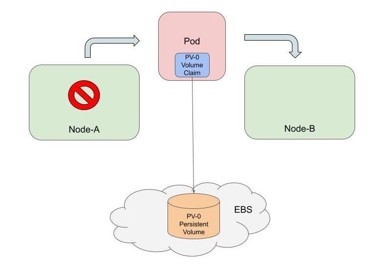
A PV continues to be retained by Kubernetes as long as the PVC is present. The PV mounts wherever the PVC goes. In the diagram below, you can see that a Pod can be removed in one node and then later recreated in another node, and the PV will follow it as long as the Pod manifest refers to the same PVC. To recycle the PV, both the Pod and the PVC have to be deleted.

Pod and State
Pods in Kubernetes are inherently stateless; when they are updated or moved from one node to another, they are destroyed and recreated. Any persistent state should be kept in attached PVs. However, early workload resources in Kubernetes only created Pods with temporary and randomized names (like http-nmx8). So when a Pod is deleted and recreated, it gets a new name. This worked great for applications whose instances were totally stateless and could be placed behind a load balancer (called a Service in Kubernetes) as shown below.
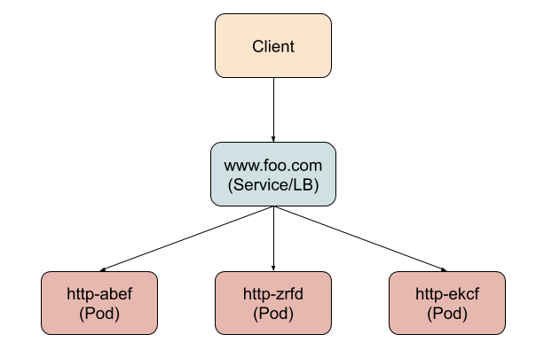
The clients only need to know the virtual hostname (or VIP) of the load balancer; there is never a need to know the actual Pod’s hostname. But when you look at HDFS and HBase, the above model does not apply. In these applications, each application instance (Pod) needs to be individually addressable by the clients directly. The client typically contacts the specific Pod expecting to find some specific data in its PV to read or modify. If the Pod changes its identity, then the client is forced to error out or refresh any cached metadata, which is disruptive to the system. In the HBase architecture diagram below you can see there are a number of components that are intertwined by this pattern of communication among them. Each arrow indicates a specific instance of an application talking to another instance of another application with a well-defined hostname.
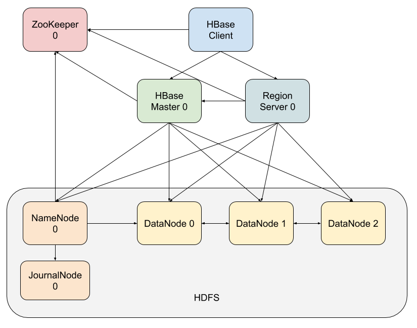
For applications like HBase (and others like Cassandra, Redis etc.) Kubernetes eventually introduced a workload resource called StatefulSets. This creates Pods with a well-defined name (and hostname). For example if you define a StatefulSet named zookeeper with three instances, then the Pods get created with the names zookeeper-0, zookeeper-1 and zookeeper-2. The number that keeps increasing in the names is called the ordinal number. If PVs are required, then PVCs with a similar ordinal based naming convention are specified within each of these Pod definitions (for example Pod zookeeper-0 can have a PVC named zk-data-0). Each PVC is bound to a different PV and that PV will be mounted wherever the uniquely named Pod lands. So now we not only have state (a PV) but also state that is permanently associated to a Pod with a fixed hostname. The fixed hostname allows all the Pod’s clients to cache information about it and locate the state associated with it.
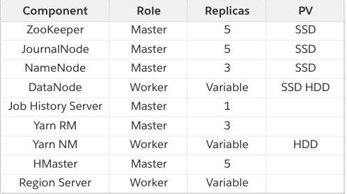
As you might have guessed from the HBase diagram above, all key components were deployed as StatefulSets in our clusters. The components are tabulated below. They are classified as master if they are meant for coordination, management and metadata components. The worker components are the ones carrying out the actual data processing.
Availability Zones (AZs)
In public cloud one can choose to run replicas of the components across fault domains to limit the impact of catastrophic failure in one domain. This usually translates to choosing to run your replicas across regions (geographically widely dispersed locations) or across availability zones (AZs), which are located within a region, but perhaps in separate buildings. Typically, latency between regions is too great for spreading replicas across them, so AZs with their low latency are the best choice for a database like HBase. We designed the component to run across three AZs.
Spreading Across AZs
Public cloud Kubernetes nodes have labels that identify the AZ and the region in which the node exists. This is leveraged while scheduling Pods on them. Two mechanisms were used in Kubernetes to guide the scheduling of Pods:
- Affinity and anti-affinity rules defined as annotations in Pod manifest. One can define the rules as preferred or required depending on how strictly they need to be enforced during scheduling. The rules specify either to attract (affinity) a Pod to a given label or repel it (anti-affinity) from the label. The target label can be on nodes or other Pods, so Pod scheduling can get influenced by the labels that are on a node or labels that are on Pods already scheduled on that node.
- Node selector allows a Pod to be scheduled only on a node or nodes that have a specific label. This is very much like the required affinity feature above, but uses much simpler syntax.
Using these mechanisms, the following rules were defined for the Pods
- Require a Pod anti-affinity that prevents Pods of the same component being on the same node. This prevents failure of one node impacting multiple Pods of a component.
- Prefer distribution of Pods of a component across AZs using AZ label anti-affinity. This is a preference and not a requirement as there are only 3 AZs and most components had more Pods than that.
- Use nodeSelector to run DataNode, RegionServer and Yarn NodeManager Pods on separate groups of nodes (more on this below).
In public cloud you can pick from nodes of different sizes (varying size of CPU and memory). You just have to define a node group with certain cpu/memory sizing and all nodes in that group would share those characteristics. One could have gone with a single standard sized node for the whole cluster (a single node group) and let Kubernetes handle allocation of Pods to the nodes. However, there were a couple of factors to consider
- We wanted worker components to have guaranteed network bandwidth for their tasks, and Kubernetes did not account for bandwidth needs while placing Pods on nodes, only CPU and memory needs. By scheduling worker Pods on dedicated nodes of a particular group you could provision bandwidth for them much more predictably.
- For Yarn NodeManagers, we wanted to be able to grow and shrink the number of nodes aggressively based on activity, but for DataNodes (and RegionServers, to a lesser extent) we wanted to be very cautious about shrinking node counts. Separate node groups allowed us to choose which components experienced more turbulence in node counts.
- We wanted Pod replicas of a given component to be on separate nodes to reduce the impact of node failure and also to have predictable bandwidth on each node. But if this were combined with a standard node, then the number of standard nodes would increase as data in the cluster grows (even if it’s cold data). This, however, would have resulted in wastage, as the DataNodes have relatively light CPU/memory requirements. By putting the Pods in nodes that are right sized for that component, we ensure that a new node is created in a size that is needed by that component which is growing in usage and hence minimize wastage.
Data replicas and AZs
DataNodes hold multiple replicas of data (three replicas, typically) for high availability. It is important to make sure that these replicas are spread across fault domains (AZs in our case) so that failure in one AZ leaves the other replicas safe. It was also important for availability reasons to make sure that the software upgrade process does not upgrade more than one replica of the same data. HDFS has topology awareness which takes feedback from a script to understand where the DataNodes are located in terms of fault domains. This was typically used to ensure that replicas ended up in DataNodes on different racks in a data center. In public cloud, we implemented a script that provided the topology of DataNodes in terms of AZs and ensured that the three replicas were across three AZs.
We also defined three separate StatefulSets for DataNodes. Each StatefulSet was responsible for Pods of a single AZ. Each StatefulSet used nodeSelector to ensure its Pods ran in nodes of a specific AZ. We did this so that we could be certain that while doing software upgrades of Pods of a particular StatefulSet, only one replica of the data is disrupted. The other two data replicas would be safely under two other StatefulSets. The diagram below shows how all the components are spread out across AZs.

In this first part of the blog we have covered introduction to concepts in Kubernetes and Public Cloud that are relevant to stateful application management. We also covered how we leveraged features in Kubernetes and Hadoop/HBase to build a highly available service. In the second part of the blog we will cover some of the shortcomings we ran into while using these technologies and how those were overcome.
Thank you to Joel Swiatek, Aditya Auradkar, and Laura Lindeman for additional review of this post!


